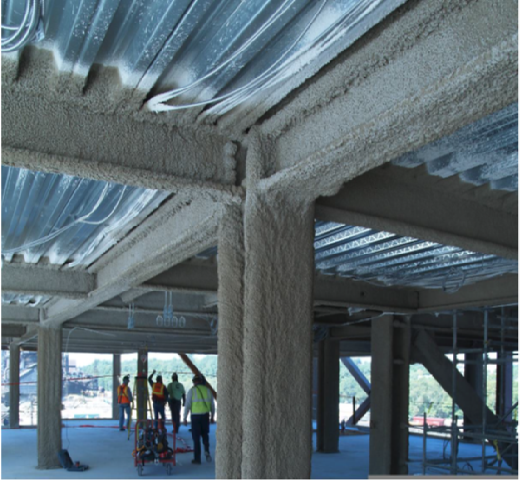
The technical name for Spray Applied Fireproofing is Sprayed Fire-Resistive Material (SFRM). It is used for passive fire protection which is used to delay (or even prevent) the failure of steel and concrete structures that are exposed to the high temperatures, during a fire..
Fireproofing features, Regulations and Challenges
The fire resistance of structures to which SFRM are applied are measured and defined by ASTM E119, called Standard Test Methods for Fire Tests of Building Construction and Materials.
The International Building Code 2018 discusses SFRM in Section 704.13. The key parameters to be inspected for fireproofing are :
Bond Strength
( As per IBC) to be measured as per ASTM 3 736 Standard Test Method for Cohesion/Adhesion of Sprayed Fire-resistive Materials Applied to Structural Members
Dry Density and Thickness
(As per IBC) to be measured asper ASTM E605 : Standard Test Methods for Thickness and Density of Sprayed Fire-Resistive Material Applied to Structural Members
Uniformity of spray texture
This is a requirement mostly by owner but also a feature of expertise to prove any one’s eyes.
Bond Strength
Bond strength was introduced aftermath of the attacks on the World Trade Centre. The objective is to check the strength of adherence of SFRM with structures. The IBC code require following norms.
HEIGHT OF BUILDING
SFRM BOND STRENGTH
0-75 feet
Min. 150 psf
75-420 feet
Min. 430 psf
Over 420 feet
Min.1,000 psf
For deciding bond strength in design, other factors considered are
shock hazards or vibration of the building due to its intended usage .
Bond strength of SFRM material
Bonding feature of the SFRM with steel depends upon Adhesion/ Cohesion force. Adhesion means the force required to be exerted to take out the plaster on the surface of steel and cohesive force means the force to be exerted to brake the plaster.
Adhesive factor depends upon
the surface profile,
member profile,
foreign contamination
Character of SFRM,
Adherence to mixing and spray process
Application skill
torsional and bending stress developed later on the member.
It may occur that the plaster may be get separate from steel but still remain as cover. On striking heavy object, this shall give sound of hallow pot.
Cohesive strength is based on the material property, application timing of slurry.
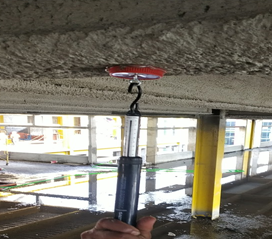
Bond strength is measures by fixing disc or cap with a hook on the spray surface. A spring gauges is used to give PULL force till the cap gets detached with material. Bond strength is calculated as force applied / area of the disc/ cap.
Density
The IBC code/ UL 263 insists for measurement of thickness along with the density of material. These two parameters are jointly responsible for providing temperature resistance to the steel structure. Some time low density require higher thickness also. Further, if density is higher, it is difficult to wither away due to weather or exposure.
The dry density of sprayed material is related to the bulk density of material, the foaming character of the material batch, mix ratio and time. With more water mixed and more foaming, the bulk density shall reduce resulting more coverage. Hence it is advisable to use optimum mixing time & water to achieve optimum wet density so that resultant bulk density achieved in spray is always more than required.
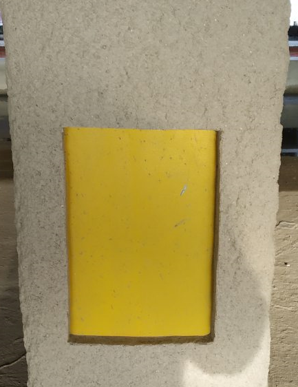
For measuring wet density a template is used to mark a area (example 200 mm x 300 mm). The fire proofing material in side the marking is taken out with a knife in a polythene. The depth of the spray is measured at 12 points inside, to find average thickness of spray. The material is now dried in a oven at 55 degree till it’s weight remain constant. Dry density is calculated by dividing Mass/ Volume.
Thickness
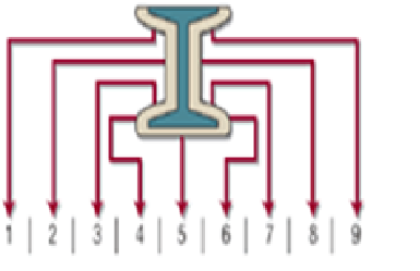
The UL Fire Resistance Directory provides ratings for various SFRM assemblies in their group 700-899. Testing agency provide the thicknesses of their products needed to meet the various hourly ratings. Thickness are measured around the beam or column at 9 or 12 point methods based on 3 side or 4 side exposure.
Average thickness of 9 points in beam shall meet minimum design thickness and no point shall not be less by 6 mm from design thickness. In practical situation, the sprayer skill must be adequate to meet this criterion. The sprayer has to deposit uniformly and also take care that it shall not be less by 6 mm at critical areas like edges of flange or upper part of the web.
Normally the sprayer has to ensure a methodical procedure,
So that every layer of spray is not less than 6-8 mm and not more than recommended.
So that, edges get enough thickness deposition,
So that no corner accumulates more material.
so that excess slurry does not flow down vertically on surface of steel member, and spray material remain on place of spray.
So that sprayed material does not fall to ground as drops .
So that every time he sprays he measures the area frequently with a gauge for achieving targeted thickness. The inspection engineer additionally confirms same for every layer of spray.
Texture:
Appearance may not be a criterion for fire proofing function but certainly there is a contract for the achieving an average texture, which is normally agreed through a demo before spray work.
The problems in spray appearance quality are
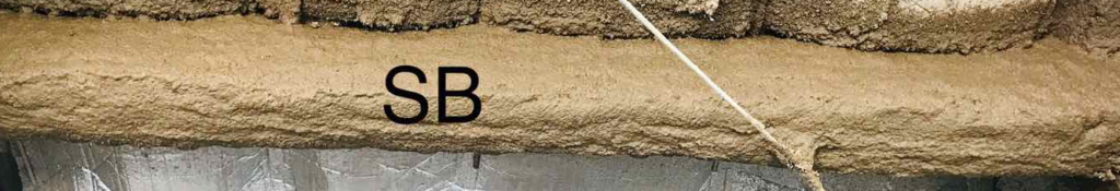
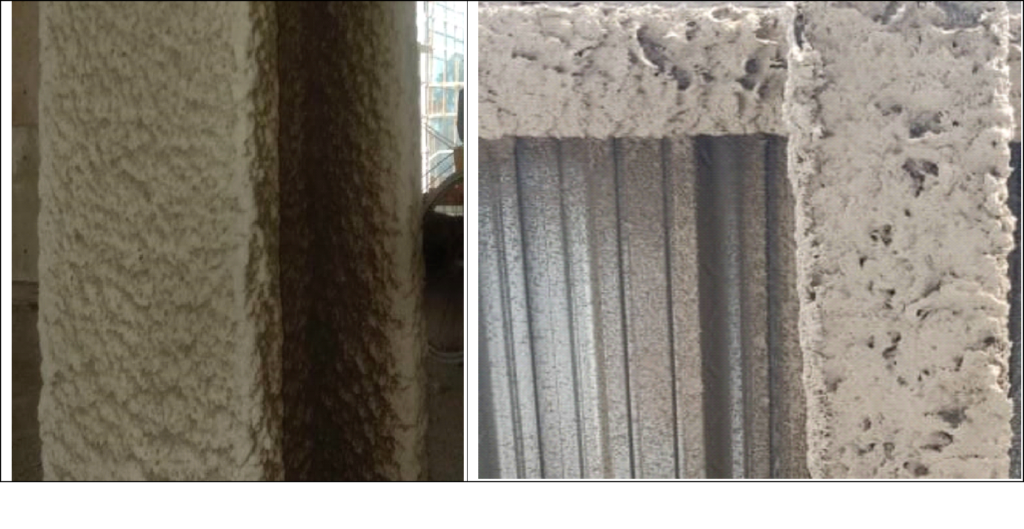
Undulation (Uneven) spray lines with thickness variation.
Large drips, sags or protruding drops or sludge surface
Mesh coming out
Thick Corner
Crack
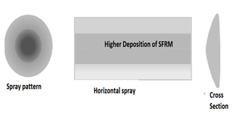
Undulation Spray
In actual situation, gun throws more material at center of the spray patch and the thickness of deposition decreases linearly towards periphery of the patch.
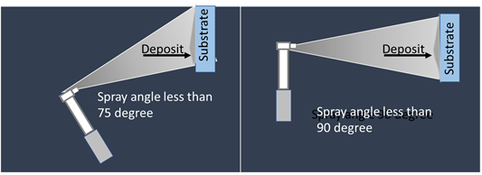
Improper Spray Angle : While spraying if spray angle 90 degree, and less than 75 degrees, following type of depositions shall happen. It may be observed that when angle is less, higher deposition is made at the edge of spray patch and that may lead to undulation.
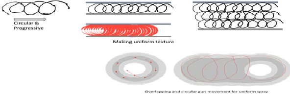
Non even spray passes : This means non symmetrical progress of hand and leaving gaps between lines of spray.This can be over come by spraying at low pressure and near to substrate. The progress of hand/ gun shall be steady and uniform. Subsequent line of spray shall be overlapped as in picture.
Other option for achieving uniform thickness with least undulation is shown in below. Here the gun is moved in clockwise manner with continuous progressive manner, such that, gun fills the center area of circle in every subsequent spray.
High air pressure can displace material already deposited due to higher water content and make undulation. Hence pressure and distance of the gun from substrate to be managed.
B. Drip or Sag Spray (Protruded from surface)
If mixing of water is more, the wet density shall be high and on spraying material shall flow downwards. The sag occurs on lower side of lower flange, On web and also on column. The wet density should be controlled at lower half of recommended range to avoid flow of sprayed material.
C. Bird nest (Mesh being seen)
Normally reinforcement should be carried at 1/3 of design thickness. However, at overlap joint of mesh or due to break of installation pin or due to uncareful mesh installation, mesh or lath remains at higher height. These deviations may be visible after the spray thickness. It is difficult to correct this defect after spray. To correct, the area is completely cleaned and mesh is again installed followed by spray process.
D. Thick Corner.
The defect is observed at joint of web and lower flange :
Spray material slides down to this corner due to gravitational flow when
The width of web is high or mesh is not applied
or material sprayed is too liquid
or spray carried is thicker than recommended for a coat.
Edge of Flange :
To have desired design thickness at edge, normally special deposition carried at these edge. Such practice makes edge of flange thick.
E. Cracks
Cracks may be developed immediately after drying or may be with period of time. The main reasons are
Change of season
Torsion stress developed on steel members during construction and load application.
Improper Curing or Immediate surface drying of spray material.
While hair cracks have no impact on fireproofing, but large crack require repairing. Repairing shall be carried following the OEM instruction. A normal rule is to have
Cut the mouth ½ inch both side.
Cut reverse V or like a key
Fill with fresh material.
SUMMERY
While defects are likely to be happened in SFRM spray, but control of defects lies on adherence to method statement , Mixing process, Equipment used, experience and skill of sprayer. Use of freshly mixed material reduces defects. For application of new SFRM , applicator should consult the OEM.